Cabin and interior structures
Seat-track interfaces, partition frames, overhead or monument supports, trim carriers, floor-edge members, and interior equipment mounting sections.
Application pathway
Application-specific aluminium sections for cabin structures, equipment frames, thermal housings, and precision aerospace assemblies.

Application guide
Aerospace extrusion applications use carefully controlled cross-sections to place material around load paths, fasteners, equipment interfaces, cable routes, seals, and thermal surfaces. Typical opportunities include cabin and ground-support assemblies, equipment frames, seat or monument structures, guide rails, housings, and heat-management components. Final material, qualification, inspection, and approval requirements remain controlled by the aircraft or equipment programme.
Seat-track interfaces, partition frames, overhead or monument supports, trim carriers, floor-edge members, and interior equipment mounting sections.
Lightweight frames, electronics housings, instrument supports, access-panel edges, and ground-support equipment structures.
Linear guides, cargo or service tracks, locating rails, protective edges, and repeated attachment interfaces.
Finned housings, cold-plate interfaces, avionics support profiles, and enclosures designed to conduct and reject heat.
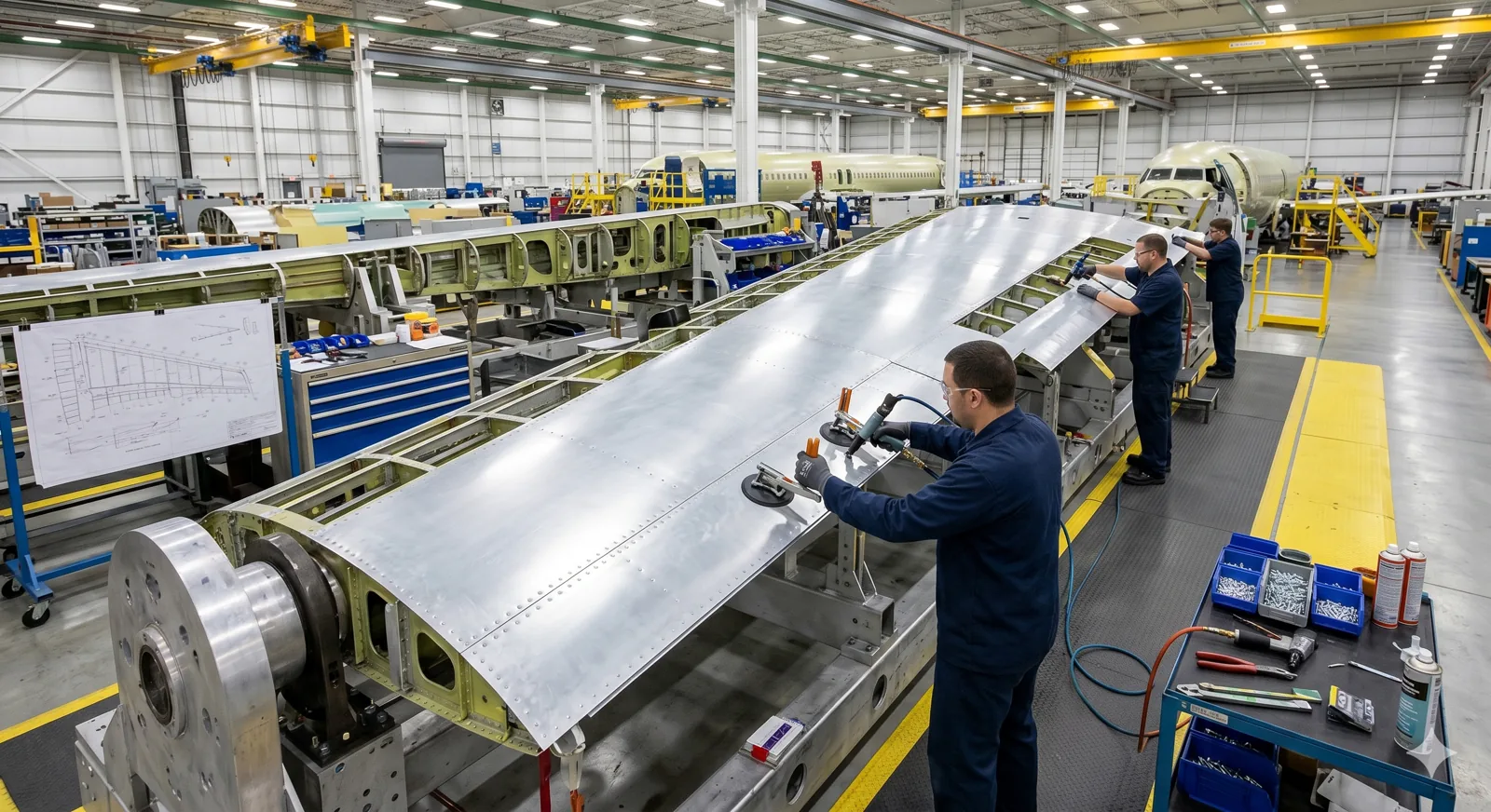
Precision assembly view
This image position is reserved for a distinct cabin frame, equipment support, guide rail, or thermal-housing view supplied for the aerospace page.
Assembly mechanics
These principles explain the role of the extrusion inside the finished assembly. Final dimensions and performance must be checked against the project design and selected hardware.
Principle 01
Ribs, flanges, hollows, and local wall thickness place stiffness around bending, attachment, bearing, and equipment-support zones.
Principle 02
Slots, screw ports, locating shoulders, cable channels, and trim retainers can combine functions that would otherwise need separate brackets.
Principle 03
The continuous extrusion is cut, drilled, milled, deburred, finished, and inspected to create local holes, pockets, end conditions, and assembly datums.
Principle 04
Approved drawings, material requirements, inspection plans, batch identification, and change control define the production and acceptance route.
Engineering fit
Common requirements
Profile response
Technical decision points
Share static loads, vibration, repeated cycles, attachment reactions, stiffness limits, and any programme-defined damage or fatigue criteria.
Material selection must follow the approved design basis, required strength, corrosion environment, joining route, finish, and procurement specification.
Identify mating faces, hole positions, straightness, twist, profile, cut length, and the inspection datum structure used by downstream machining.
Bolts, inserts, rivets, bonding, welding, adjacent materials, sealants, and galvanic-isolation details should be considered together.
Visible surfaces, coating or conversion requirements, burr limits, corner radii, handling protection, and cleanliness affect acceptance.
Programme approvals, first-article needs, material certificates, inspection records, serialization, and supplier controls must be defined by the customer.
Practical technical facts
A purpose-designed section can reduce material removal compared with machining the same functional shape from a larger solid block.
Hollows, ribs, and local reinforcement can place material where it contributes to stiffness while opening low-stress regions.
A suitable aluminium shape is not automatically an approved flight component; the customer controls design substantiation and qualification.
Die, alloy, temper, process, finish, machining, or inspection changes may require review before they enter an approved supply route.
Profile pathways
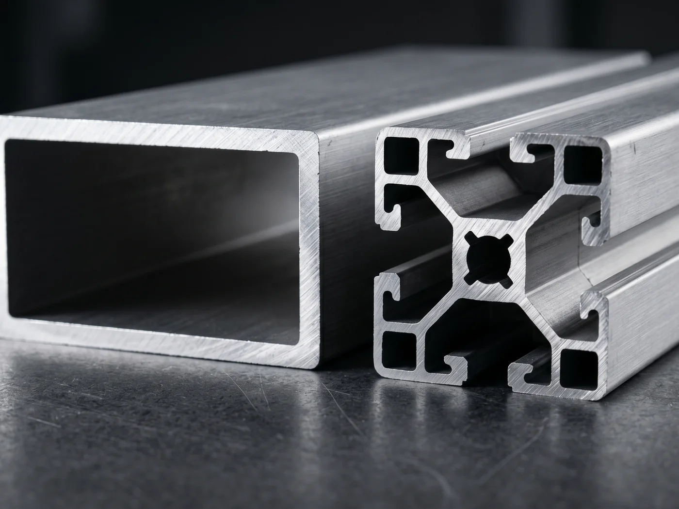 Machinery & Fabrication
Structural, thermal-management, enclosure, and automation sections for industrial applications.
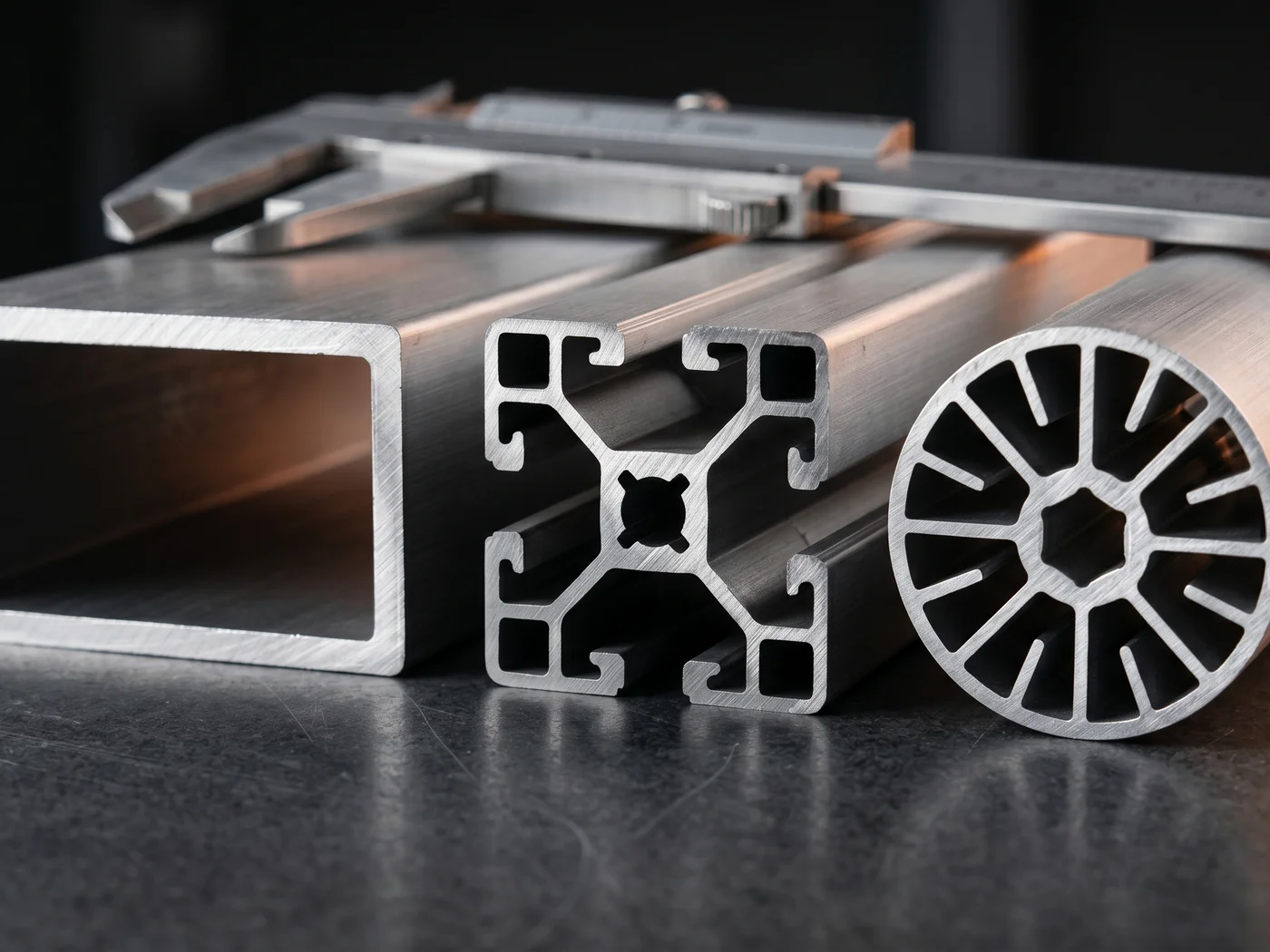 Designed Around Your Application
Application-specific profiles developed from drawings, samples, performance needs, and fabrication constraints.
Drawing-led RFQ
Send the cross-section and application context for manufacturability review. Customer-specific geometry remains confidential and is not published as a case study.