Heat sinks and thermal housings
Finned sections, base plates, driver housings, inverter bodies, power-supply cases, and electronics enclosures that spread and reject heat.
Application pathway
Heat sinks, server-rack members, enclosures, LED channels, and equipment housings designed around thermal and assembly needs.
Application guide
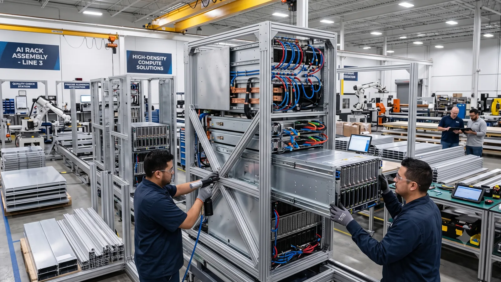
Electronics extrusions use aluminium geometry to conduct heat, protect components, create rack and enclosure structures, guide boards or cables, retain lenses and panels, and provide repeatable mounting surfaces. Common applications include heat sinks, server and telecom racks, power-electronics housings, LED channels, control enclosures, instrument cases, and equipment frames.
Finned sections, base plates, driver housings, inverter bodies, power-supply cases, and electronics enclosures that spread and reject heat.
Vertical posts, rails, chassis members, card guides, cable-management profiles, doors, bezels, and equipment-support frames.
Channels that support LED boards, lenses, diffusers, end caps, mounting clips, wiring, and heat transfer in linear lighting.
Split housings, slide-in panels, PCB guides, faceplate frames, sensor bodies, control boxes, and modular equipment cases.
Thermal profile field view
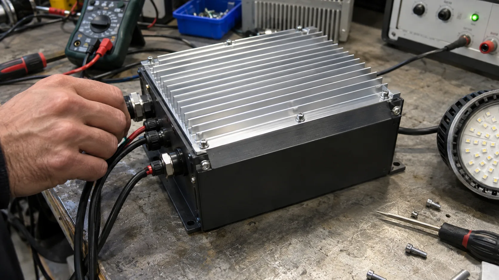
This illustrative workbench visual shows a finned aluminium heat sink mounted to a power-electronics enclosure. Thermal duty, interface flatness, airflow, fin geometry and EMC or grounding requirements require application-specific review.
Assembly mechanics
These principles explain the role of the extrusion inside the finished assembly. Final dimensions and performance must be checked against the project design and selected hardware.
Principle 01
A thermal interface connects the component or board to the profile so heat can spread through the extrusion.
Principle 02
Fin count, height, spacing, thickness, orientation, and airflow influence how effectively heat passes from the profile to the surrounding air.
Principle 03
Slots, card guides, screw ports, lens seats, cable paths, and panel grooves organize assembly without many separate brackets.
Principle 04
Cut-outs, tapped holes, connector openings, end preparation, grounding points, and finish create the final equipment-specific housing.
Alloy guidance
The final alloy and temper are confirmed against the controlled drawing, required strength, extrusion geometry, fabrication route, finish, and service environment.
Alloy status
Availability, temper, tolerances, and suitability are confirmed during technical review.
Engineering fit
Common requirements
Profile response
Technical decision points
Share heat load, component limit, ambient range, interface location, airflow direction, fan curve if used, and allowable temperature rise.
Natural or forced convection, orientation, blockage, dust, fin spacing, surrounding clearance, and enclosure ventilation affect performance.
PCB dimensions, rack standard, mounting holes, connector positions, lens or diffuser, seals, fans, filters, and service access drive the section.
Grounding, bonding, electrical isolation, coating removal at contact points, shielding strategy, and creepage or clearance remain system-design responsibilities.
Anodizing, powder coating, cosmetic grade, emissivity needs, contact surfaces, masking, colour, and coating thickness should be specified.
Burr control, chips, cutting fluid residue, flatness, thread quality, connector cut-outs, and protected surfaces affect electronics assembly.
Practical technical facts
A large heat sink still needs a low-resistance path from the heat source and enough airflow around the fins.
Natural-convection fins generally need an orientation and clearance that allow warmer air to rise and cooler air to replace it.
Board guides, screw ports, panel grooves, cooling fins, mounting feet, and finished outer surfaces can share one cross-section.
Finish build-up can change tight fits and electrical contact, so masking and contact zones should be defined before production.
Drawing-led RFQ
Send the cross-section and application context for manufacturability review. Customer-specific geometry remains confidential and is not published as a case study.
Electrical and electronics context
Electrical aluminium profiles and electronics housings require coordinated geometry, heat flow, interfaces, finish, fabrication, and electrical design responsibility.
An extruded aluminium enclosure, PCB housing, amplifier enclosure, LED aluminium profile, or equipment housing should be specified from the board, connector, mounting, ventilation, finish, and machining requirements.
Switchgear profiles, electrical panel sections, and related power-system components require project-specific electrical and safety review. Website application language does not establish conductivity, insulation, rating, or compliance.