Module frames
Perimeter protection and mounting interfaces for photovoltaic laminates.
Application pathway
Corrosion-resistant structural profiles designed for scalable field assembly.
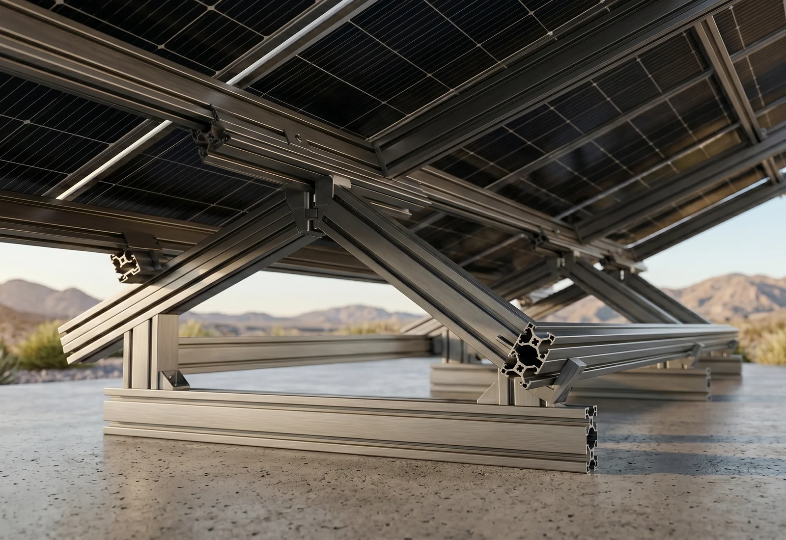
Application guide
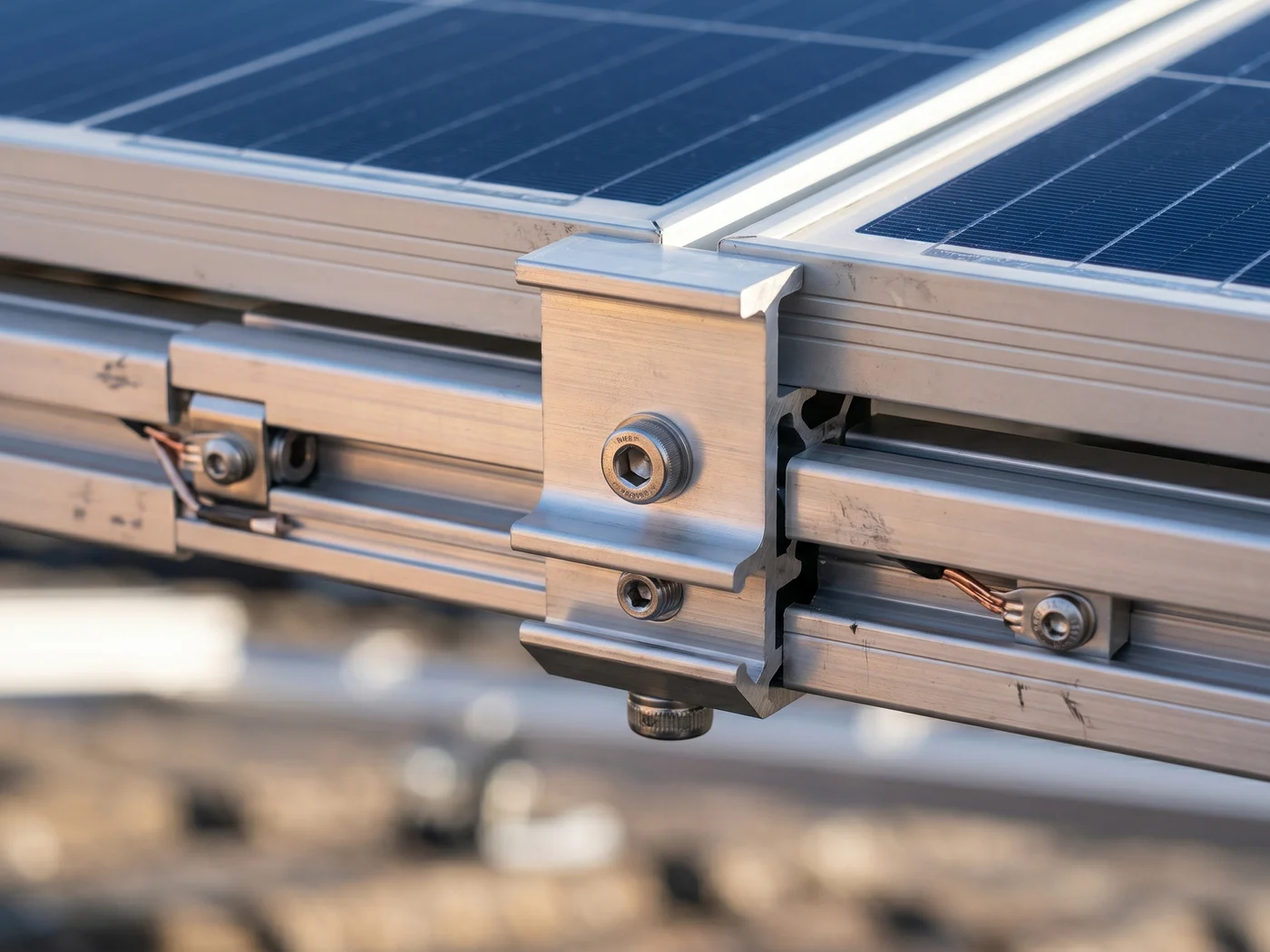
Solar aluminium profiles connect modules to roofs, canopies, or ground structures through frames, rails, clamps, channels, brackets, splices, and fasteners. The profile geometry must support efficient field assembly while the complete mounting assembly is checked for project loads, movement, corrosion, and electrical requirements.
Perimeter protection and mounting interfaces for photovoltaic laminates.
Rails and clamps connecting modules to roof hooks, brackets, purlins, or standing-seam interfaces.
Long rails, channels, supports, and connection members for repeated table or row assembly.
Custom structural and trim sections for shade structures, walkways, equipment supports, and service routes.
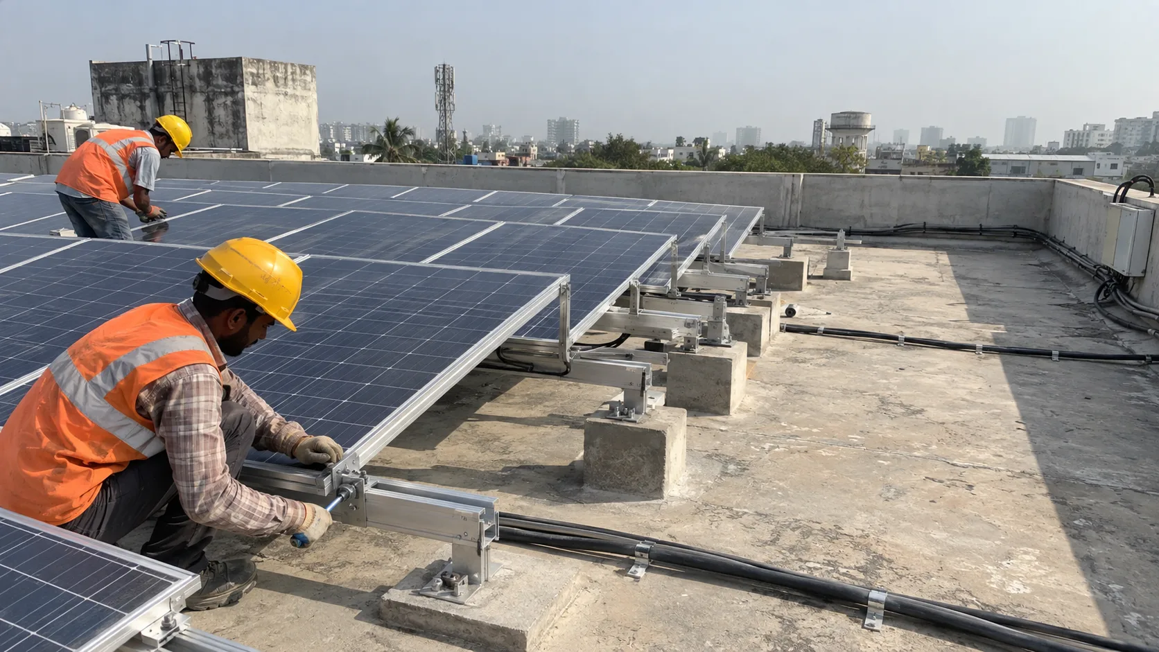
Solar installation field view
This illustrative rooftop visual shows installers handling aluminium rails and brackets beside solar modules. It is indicative only: spans, loads, clamp zones, fasteners, grounding and roof interfaces require project-specific engineering.
Catalogue evidence
Use the published code and section as an enquiry reference. Final system compatibility still depends on the complete drawing, hardware and application.
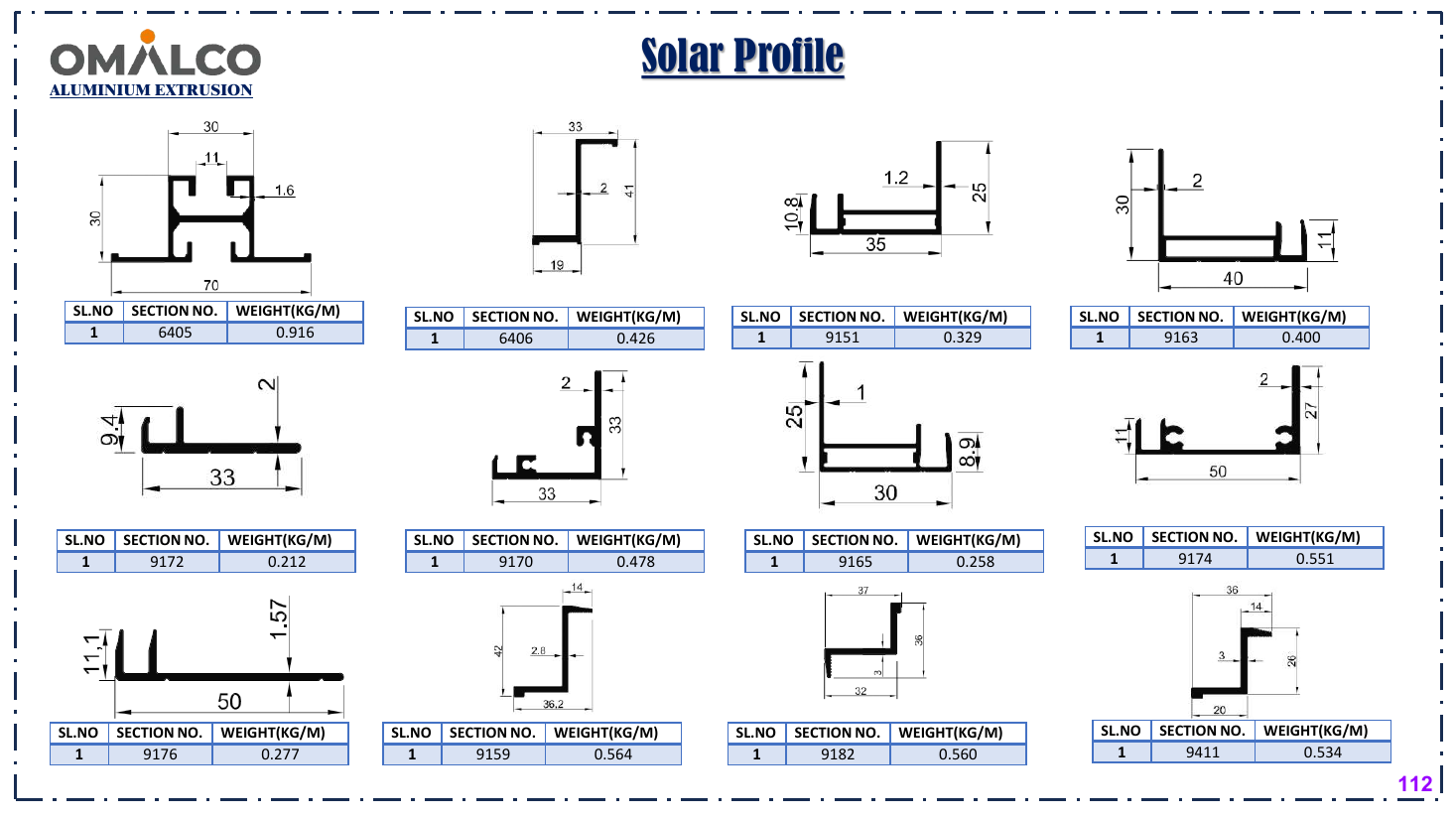
Solar profile references I
Published cross-sections that can be identified by code before an application-specific review.
Master catalogue page 112
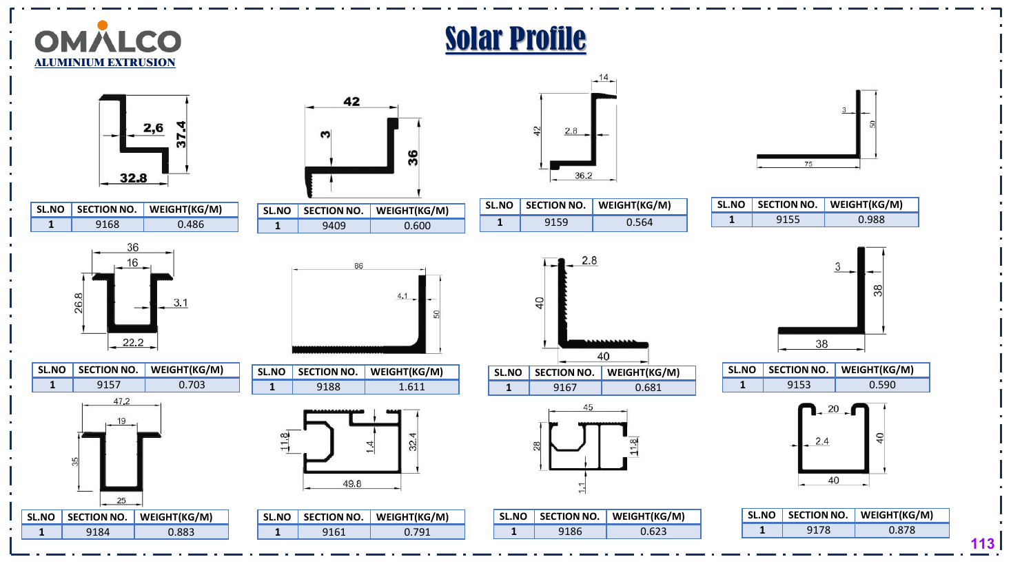
Solar profile references II
Additional published solar sections; the complete mounting assembly still requires project design checks.
Master catalogue page 113
Assembly mechanics
These principles explain the role of the extrusion inside the finished assembly. Final dimensions and performance must be checked against the project design and selected hardware.
Principle 01
Clamps engage approved module zones and pass wind, snow, and self-weight actions into the supporting rail.
Principle 02
The rail resists bending and deflection between roof attachments, purlins, posts, or ground-structure connections.
Principle 03
Bolts, nuts, brackets, splices, and anchors transfer rail reactions into the roof or primary support.
Principle 04
Splices, slots, drainage, roof interfaces, and material compatibility address long-run expansion and outdoor exposure.
Engineering fit
Common requirements
Profile response
Technical decision points
Wind, snow, dead load, uplift, span, support spacing, and serviceability must come from the project design basis.
Frame geometry, approved clamp zones, edge and mid clamps, bolt access, and installation torque must align.
Substrate, waterproofing, attachment spacing, bracket geometry, tolerance, and drainage require project-specific details.
Fasteners, adjacent metals, coatings, runoff, salt or industrial exposure, and isolation materials should be reviewed.
Electrical continuity and grounding components must follow the project electrical design and applicable requirements.
Stock lengths, splice positions, cut plans, packing, lifting, thermal breaks, and tool access affect field productivity.
Practical technical facts
Capacity depends on span, support, clamp, splice, fastener, and attachment details, not the extrusion alone.
Temperature change can create significant accumulated movement across long rail runs and repeated rows.
Profile orientation, slots, end conditions, and roof details should avoid trapped water and blocked runoff.
Repeatable hardware, clear access, controlled part count, and logical packing reduce installation error.
Profile pathways
 Renewable Infrastructure
Rails, frames, channels, clamps, and structural sections for solar and infrastructure projects.
 Designed Around Your Application
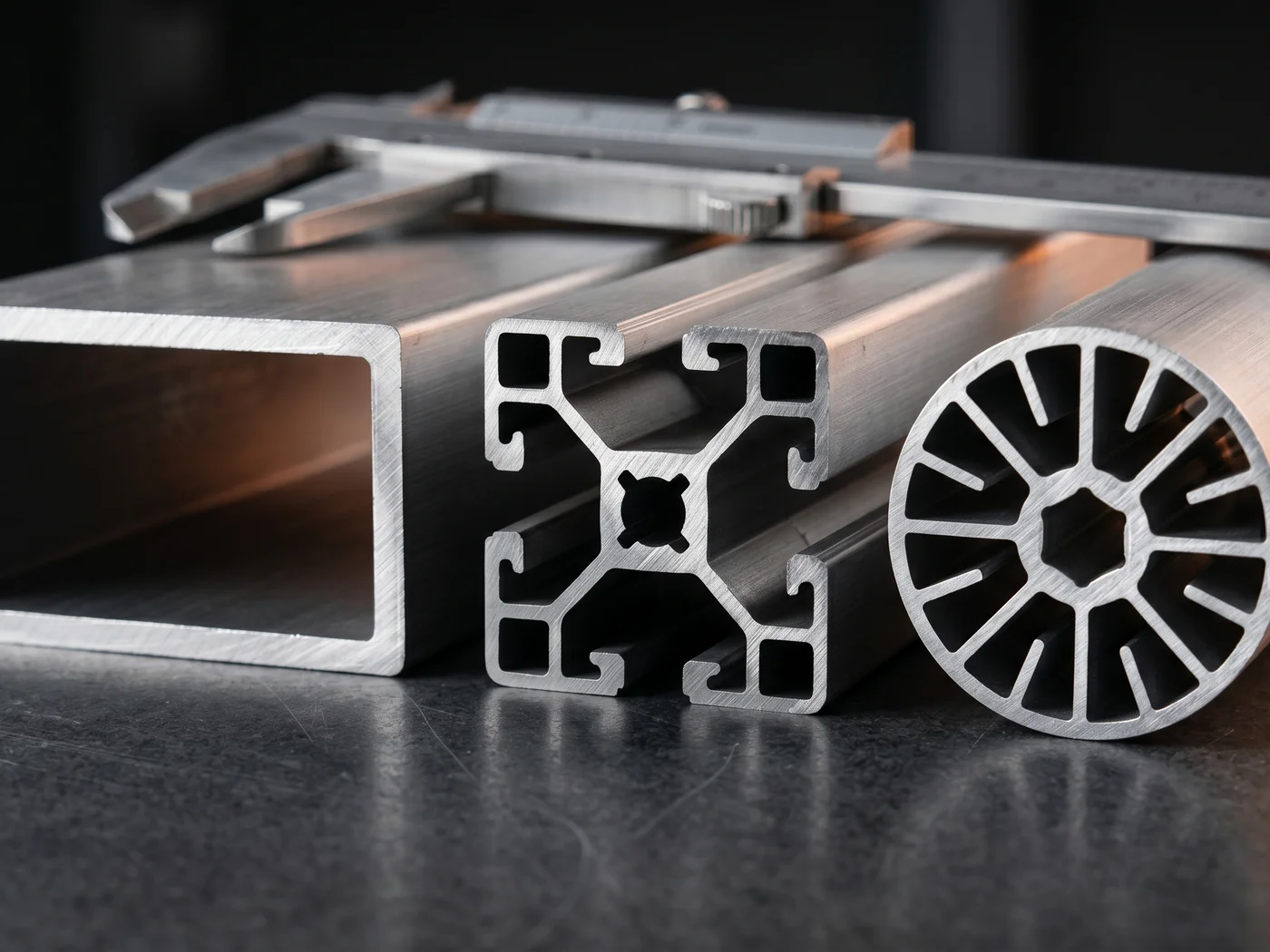
Application-specific profiles developed from drawings, samples, performance needs, and fabrication constraints.
Drawing-led RFQ
Send the cross-section and application context for manufacturability review. Customer-specific geometry remains confidential and is not published as a case study.